EN 10216-2 1.0471 20MnNb6 Seamless Steel Tubes
EN 10216-2 1.0471 20MnNb6 Seamless Steel Tubes
EN 10216-2 1.0471 20MnNb6 Seamless Steel Tubes for pressure purposes (power plant boiler tubes/oil refinery boiler tubes)
Standard:BS EN 10216-2:2013
Seamless steel tubes for pressure purposes — Technical delivery conditions Part 2: Non-alloy and alloy steel tubes with specified elevated temperature properties.
EN 10216-2 1.0471 20MnNb6 Seamless Steel Tubes Quick Details
Manufacture:Seamless process
Wall thickness(WT): 2.1mm——50 mm.
Outer diameter (OD): 21 mm——509mm
Length: 6M or specified length as required.
Ends: Plain End, Beveled End, Treaded
Additional Info
Port of Shipment: Tianjin,Shanghai,as required China
Payment Terms:T / T, LC
Delivery: 25-45 days after payment
Surface: Tubes will be varnished to prevent rust.
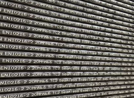
Marking: Standard + Steel Grade + Size + Heat No + Lot No
Package: Bundles (hexagonal),Wooden Boxes,Crates (steel/wooden) or as required
Manufacturing process
steel making process
1.0471 20MnNb6 steel is a carbon (non-alloy) steel
1.0471 20MnNb6 Steels shall be fully killed.
The tubes shall be manufactured by a seamless process.
We will hot work or cold work the tube according to the actual requirements.
If cold-finished,tubes should be cold-finished prior to heat treatment.
| Steel Grade |
Heat treatment a |
Austenizing | Tempering | |||
| Steel Name | Steel Number | Temperature °C |
Cooling Medium |
Temperature °C |
Cooling medium |
|
| 20MnNb6 | 1.0471 |
+N (b) |
900 to 960 | Air | - | -- |
|
a +N = Normalizing, +NT = Normalizing + Tempering, +QT = Quenching + Tempering (air or liquid), +I = Isothermal Annealing. b Normalizing includes Normalizing Forming. Normalized Forming shall be carried out in a temperature range from 880 °C to 1 000 °C. |
||||||
Chemical Composition of EN 10216-2 1.0471 20MnNb6 Seamless Steel Tubes
| Steel grade |
Steel number |
C | Si | Mn |
P max |
S max |
| 20MnNb6 | 1.0471 | ≤0.22 | 0.1 5-0.35 | 1 .00-1 .50 | 0.025 | 0.020 |
| Cr | Mo | Ni | Al tot | Cu | Nb |
Ti max |
| - | - | - | ≤ 0.060 | ≤0.30 | 0.01 5-0.1 0 | - |
In order to facilitate subsequent forming operations, an agreed maximum copper content lower than indicated and an agreed specified maximum tin content shall apply
Mechanical Properties of EN 10216-2 1.0471 20MnNb6 Seamless Steel Tubes
| Steel Grade | Upper yield strength or proof strength R eH or Rp 0,2 for Wall Thickness T min. |
Tensile Strength Rm |
Elongation A min. % a |
|||||
| Steel Name | Steel Number | T ≤ 16 | 16 < T ≤ 40 | 40 < T ≤ 60 | 60 < T ≤ 100 | l | t | |
| MPa * | MPa * | MPa * | MPa * | MPa * | ||||
| 20MnNb6 | 1.0471 | 355 | 345 | 335 | - | 500 to 650 | 22 | 20 |
| Steel Grade | Impact properties | |||||
|
Minimum average absorbed energy KV 2 J at a temperature of °C |
||||||
| Steel Name | Steel Number | l | t | |||
| 20 | 0 | -10 | 20 | 0 | ||
| 20MnNb6 | 1.0471 | - | 40 | - | - | 27 |
Impact energy shall be verified
Minimum proof strength R p0,2 at elevated temperature of EN 10216-2 1.0471 20MnNb6 Seamless Steel Tubes
| Steel Grade |
Wall thickness mm |
Minimum proof strength R p0,2 MPa at a temperature of °C | ||||||||
| Steel name | Steel number | 100 | 150 | 200 | 250 | 300 | 350 | 400 | 450 | |
| 20MnNb6 | 1.0471 | ≤60 | 312 | 292 | 264 | 241 | 219 | 200 | 186 | 174 |
Dimensions tolerances of EN 10216-2
Tolerances on outside diameter and wall thicknes
| Outside Diameter D mm |
Tolerances on D |
Tolerances on T for a T/D ratio | |||
| ≤ 0,025 |
> 0,025 ≤ 0,050 |
> 0,050 ≤ 0,10 |
> 0,10 | ||
| D ≤ 219,1 |
± 1% or ± 0.5mm whichever is the greater |
± 12,5% or ± 0.4mm whichever is the greater | |||
| D > 219,1 | ± 20% | ± 15% | ± 12,5% | ± 10% a | |
| a For outside diameters D ≥ 355,6 mm it is permitted to exceed the upper wall thickness locally by a further 5% of the wall thickness T | |||||
Tolerances on inside diameter and wall thickness
| Tolerances on inside diameter | Tolerances on T for a T/d ratio | |||||
| d | d min | ≤ 0,03 |
> 0,03 ≤ 0,06 |
> 0,06 ≤ 0,12 |
> 0,12 | |
| ± 1% or ± 2 mm whichever is the greater |
(+ 2% ,0)or (+ 4 mm,0) |
whichever is the greater | ± 20% | ± 15% | ± 12,5% | ± 10% a |
| a For outside diameters D ≥ 355,6 mm it is permitted to exceed the upper wall thickness locally by a further 5% of the wall thickness T | ||||||
Tolerances on outside diameter and minimum wall thickness
| Outside diameter D mm | Tolerances on D | Tolerances on T min for a T min /D ratio | |||
| ≤ 0,02 |
> 0,02 ≤ 0,04 |
> 0,04 ≤ 0,09 |
> 0,09 | ||
| D ≤ 219,1 |
± 1% or ± 0.5mm whichever is the greater |
(+ 28%,0) or (+ 0.8 mm,0) whichever is the greater | |||
| D > 219,1 |
+ 50% 0 |
+ 35% 0 |
+ 28% 0 |
+ 22% a 0 |
|
| a For outside diameters D ≥ 355,6 mm it is permitted to exceed the upper wall thickness locally by a further 5% of the wall thickness T | |||||
Tolerances on inside diameter and minimum wall thickness
|
Tolerances on inside diameter |
Tolerances on T min for a T min /d ratio |
|||
| d | d min | ≤ 0,05 |
> 0,05 ≤ 0,1 |
> 0,1 |
|
± 1% or ± 2 mm whichever is the greater |
(+2%,0) or (+ 4 mm,0) whichever is the greater |
+ 35% 0 |
+ 28% 0 |
+ 22% a 0 |
| a For outside diameters D ≥ 355,6 mm it is permitted to exceed the upper wall thickness locally by a further 5% of the wall thickness T | ||||
Tolerances on exact lengths
Dimension in mm
| Length L | Tolerance on exact length |
| L ≤ 6000 |
+10 0 |
| 6000 < L ≤ 12 000 |
+15 0 |
| L > 12 000 |
+ by agreement 0 |
Straightness
The deviation from straightness of any tube length L shall not exceed 0,001 5 L. Deviations from straightness over any one metre length shall not exceed 3 mm.
Preparation of ends
The tubes shall be delivered with bevelled ends (see Figure 1). The bevel shall have an angle α of 30°(+5°,0°) with a root face C of 1,6 mm ± 0,8 mm, except that for wall thickness T greater than 20 mm, an agreed alternative bevel may be specified.
specified.

TESTINGS
(1)Chemical analysis
(2)Tensile test(Tensile test at room temperature, Tensile test at elevated temperature)
(3)Flattening test
(4)Ring tensile test
(5)Drift expanding test
(6)Ring expanding test
(7)Impact test
(8)Leak tightness test(Hydrostatic test, Electromagnetic test)
(9)Dimensional inspection
(10) Visual examination
(11) Non-destructive testing
Note:
The choice of flattening or ring tensile test and of drift expanding test or ring expanding test is at the manufacturer’s discretion.
MARKING
Marking to be applied
The marking shall be indelibly marked on each tube at least at one end. For tubes with outside diameter D ≤ 51 mm the marking on tubes may be replaced by the marking on a label attached to the bundle or box.
Example of marking:
X - EN 1021 6-2 - 20MnNb6 - TC1 - Y- Z 1 - Z 2
where:
- X is the manufacturer's mark;
- TC1 is the designation of the test category 1 ;
- Y is the cast number or a code number;
- Z 1 is the mark of the inspection representative;
- Z 2 is the identification number.
Marking can be customized according to customer requirements
PROTECTION
The tubes will be delivered with A temporary protective coating or durable coating and/or lining
![field:title/]](/uploads/220805/1-220P511543cX.jpg)
![field:title/]](/uploads/250314/1-250314120549418.jpg)
![field:title/]](/uploads/230628/1-23062QK445208.jpg)
![field:title/]](/uploads/191012/1-19101215415K29.jpg)
![field:title/]](/uploads/191012/1-191012154122540.jpg)
![field:title/]](/uploads/220419/1-2204191914494F.png)
![field:title/]](/uploads/211026/1-2110261KF4F4.jpg)