Membrane Water Wall Panel|Boiler Membrane Wall
Membrane Water Wall Panel for Boiler
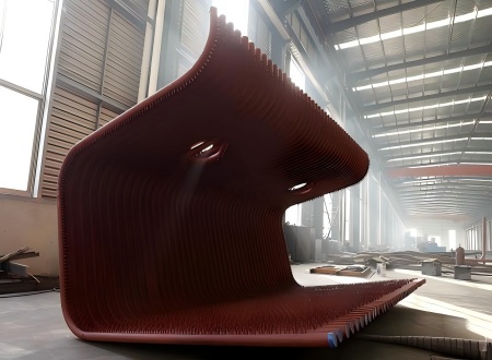
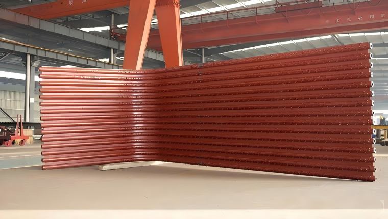
The Membrane water wall panel is the main heating part of the boiler.Which is composed of finned tubes welded together.
The membrane water wall panel refers to a water-cooled wall composed of an airtight tube panel welded together from flat steel and tubes. Membrane water walls ensure good furnace tightness and can significantly reduce the furnace leakage coefficient in negative pressure boilers, improving combustion conditions within the furnace. It increases the effective radiant heating area, thereby saving steel consumption.
Membrane Water Wall Panel Quick Details
| Product Name | Membrane water wall panel |
| Applied Area | Water tube boiler |
| Material |
- Carbon Steel : 20#, 20G, A179 , A192, A210 A1, C, A106 GrA, GrB etc.. - Alloy Steel : 15CrMoG, T5,P9,T9,T11,T22,T91,16Mo3,13CrMo4-5,10CrMo9-10 etc.. - Stainless Steel: TP304/304L,TP316/TP316L, TP347 etc... |
| Standard | China GB, ASME |
| Manufacturer Grade | China A Grade, ABS Certificated, TUV Certificated |
| Working Temperature | Saturation Temperature |
| Tube Specification |
- Common use : Φ42, Φ51, Φ57, Φ60 mm - Other |
| Color: | Customized |
| Size: | As per Customer requirements |
| Tube Thickness | As per Customer requirements |
| Tube Pitch (c-c) | 95 mm, 100 mm, 105 mm, 110 mm |
| Steel Flat Thickness | As per Customer requirements |
| Bending | Panel Bending |
| Welding | Automatic GMAW, Automatic SAW |
| Welding NDT | 100% RT on tube butt welding |
| Air Tightness | Excellent |
| Brick Work | Not Required |
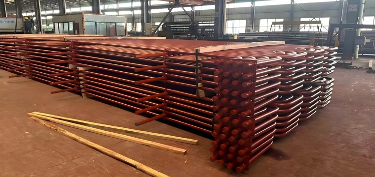
We can manufacture various types of membrane water wall panels according to drawings.
The assembly characteristics of a membrane water wall panel are:
1. After the segmented tube panels are hoisted onto the assembly frame, the width, length, flatness, and diagonals of the tube panels must be checked and adjusted. If the width of the tube panel is greater or less than the specified size, the fins can be cut to an appropriate length, adjusted to the specified size, and then re-welded. 1. When the diagonal difference of the pipe bank exceeds 10mm, the fins between the pipes at the larger end can be cut to reduce the pipe spacing to eliminate the diagonal difference before welding the fins back in place. If the unevenness of the pipe bank exceeds the allowable range, a gantry crane can be used with jacks for pressure correction.
2. The butt welding of pipe banks differs from the butt welding of individual pipes. The weld joint of a single pipe shrinks by approximately 1-2mm after welding, which has no impact on other pipes. However, pipe banks are different. When butt welding two sections of pipe banks, if welding is done sequentially from one side to the other, the deformation caused by the last pipe welded will be significant. Therefore, before butt welding, the butt gap should be fully measured and categorized as too small, moderate, or too large. If the butt gap is too large or too small, the method of cutting the pipe and replacing it with a shorter, appropriately sized pipe must be adopted. 1. When butt welding, the smallest possible gap should be selected from the suitable gaps. Due to welding shrinkage, pipes with slightly larger gaps will become weldable. To reduce welding shrinkage deformation, symmetrical and cross-welding methods should be used.
2. The lower part of the front and rear water-cooled walls has the furnace bottom (cold ash hopper section), and the upper part of the rear water-cooled wall has a flame deflector. Therefore, the assembled components are relatively large and have special shapes, making assembly difficult.
3. The single-tube ball of the rear water-cooled wall differs from other heating surface tubes. Because the rear water-cooled wall has a flame deflector at the upper header, the number of bent tubes in the flame deflector is the same as the number of tubes in the rear water-cooled wall. To increase the rigidity of the flame deflector, a considerable number of spaced straight tubes are also installed there (in most furnace types). At the intersection of the flame deflector and the straight tubes, a cast steel tee of equal diameter (three-way branch) is installed. A throttling ring with a Φ5mm or Φ10mm orifice is installed at the connection between the straight tube and the upper header. In this way, most of the working fluid flows through a curved tube, which is beneficial for cooling the flame deflector. A small portion of the working fluid flows through a straight tube, ensuring that the straight and curved tubes have corresponding expansion amounts to reduce internal stress. Therefore, the difficulty of ball passage increases.
Welding in Membrane Water Wall Panels involves both gas-shielded welding (GSW) and submerged arc welding (SAW).
GSW and SAW each have their own advantages and disadvantages. The choice between GSW and SAW depends on the company's characteristics and market positioning.
GSW: Shallow penetration and light pollution, giving SAW a broad development space. Currently, SAW is replacing GSW in membrane wall welding.
Advantages of Membrane Water Wall Panels:
1) Membrane Water Wall Panels provide the most thorough protection for the furnace wall. Therefore, the furnace wall only needs insulation material, not refractory material, greatly reducing the thickness and weight of the furnace wall, simplifying the furnace wall structure, and reducing the overall weight of the boiler.
(2) Membrane Water Wall Panels also feature good airtightness, adapting to the requirements of positive pressure combustion in boilers, reducing slagging and air leakage, minimizing flue gas heat loss, and improving boiler thermal efficiency.
(3) They can be welded into components by the manufacturer for shipment, allowing for quick and convenient installation.
(4) Boilers using membrane wall structures are easy and simple to maintain, significantly extending the boiler's service life.
Membrane Water Wall Panel Manufacturing Process:
The manufacturing process of Membrane Water Wall Panels includes: shot blasting or polishing → pipe cutting → end milling → straight pipe extension → 100% RT cutting → weld seam cutting and grinding → pipe and flat steel angle weld cutting → 100% visual inspection → marking → bend cutting → hole cutting → welded pipe bend cutting → 100% RT cutting → sealing plate cutting → marking correction → edge grinding and allowance cutting → chamfering → water pressure cutting → ball cutting → painting and packaging.
Material Preparation for Tubes and Flat Steel
Since the most crucial manufacturing technology for membrane wall tube panels is the welding of bare tubes and flat steel, the surface quality of the tubes and flat steel is paramount. Before entering the welding machine, the tubes must undergo surface cleaning using a straight tube polishing (polishing) cleaning machine to ensure welding quality.
The tube panel consists of multiple tubes and flat steel. Tubes and flat steel purchased from steel mills have manufacturing tolerances. To eliminate these tolerances and ensure that the cumulative tolerances after assembly do not exceed limits, ultimately achieving precise control of the tube panel's dimensions, the width of the flat steel must be precision-finished, and its surface cleaned to meet welding requirements. The flat steel is typically processed using a high-strength flat steel finishing and cleaning machine. This equipment is equipped with dedicated finishing and straightening wheels to ensure accurate width dimensions and straight, untwisted flat steel, facilitating welding.
Welding details of Membrane Water Wall Panels
Welding of Fillet Welds in Membrane Water Wall Panels Welding Methods for Membrane Water Wall Panels with Flat Steel Structures The main welding processes used for membrane water wall panel structures with flat steel structures are as follows:
1. Automatic Metallic Anode (MAA) Gas Shielded Welding The shielding gas mixture consists of 85%–90% Ar and 15%–10% CO2. In the equipment, the pipe and flat steel are pressed together by upper and lower rollers and conveyed forward. Multiple welding torches can be used to weld simultaneously on both the upper and lower surfaces.
2. Fine Wire Submerged Arc Welding This equipment is a fixed frame welding workstation. The machine tool has functions such as positioning, clamping, feeding, welding, and automatic flux recovery of the steel pipe and flat steel. It is generally equipped with 4 or 8 welding torches to simultaneously complete the welding of 4 or 8 fillet welds in the horizontal position. This technology is simple to operate and has low requirements for the surface of the pipe and flat steel, but it can only weld on one side in the horizontal position and cannot achieve simultaneous welding on both the upper and lower surfaces.
3. Semi-automatic Gas Metal Arc Welding (GMAW)
When using this method, the tube screen should first be tack welded and fixed, and then welding should be performed manually using a welding torch. This welding method cannot weld both the top and bottom surfaces simultaneously, nor can it achieve continuous and uniform welding with multiple welding torches, making it difficult to control welding deformation. When using semi-automatic GMAW for tube screen welding, it is essential to carefully select the welding sequence to minimize welding deformation. Semi-automatic GMAW is commonly used for fillet welds of sealing flat steel at local openings on the tube screen, as well as fillet welds of irregularly shaped tube screens such as cold ash hoppers and burner nozzles.
The GMAW automatic welding production line for membrane wall tube screens represents the world's most advanced membrane wall tube screen manufacturing technology and equipment. From tube feeding, flat steel uncoiling, finishing, and leveling, to welding, everything can be automatically controlled. Upper and lower welding torches can weld simultaneously, resulting in minimal welding deformation and almost no need for post-weld correction. This ensures accurate tube screen dimensions, excellent fillet weld quality, aesthetically pleasing weld formation, high welding speed, and high production efficiency.
We can manufacture various types of membrane water wall panels according to drawings.
Please fill the following form.