JIS G3461 Carbon Steel Tubes for Boiler and Heat Exchanger
JIS G3461
Carbon Steel Tubes for Boiler and Heat Exchanger
1. Scope
This Japanese Industrial Standard specifies the carbon steel tubes, hereinafter referred to as the "tubes", used for exchanging heat on the inside and outside of the tube, such as water tubes, smoke tubes, superheater tubes, air preheater tubes, etc. of the boiler, and heat exchanger tubes, condenser tubes, catalyzer tubes, etc. used in chemical and petroleum industries.
However, it is not applicable to the steel tubes for heating furnace and steel heat exchanger tubes for low temperature service.
Remarks
The purchaser may designate in addition to the items specified in this text, by prior agreement with the manufacturer, part or all of the items in the supplementary quality requirements Z1, Z2, Z3 and Z4 specified in Appendix 1 and the item of the U-bend tube specified in Appendix 2.
The units and numerical values given in { } in this Standard are based on the International System of Units (SI) and are appended for informative reference.
2.Classes and Symbols
The tube shall be classified into 3 grades and their class symbols shall be as given in Table 1.
Table 1 Classes and Symbols
| Standard | Classes (Grades) |
| JIS G3461 | STB 340 |
| STB 410 | |
| STB 510 |
3.Method of manufacture
Heat Treatment
| Grade | Heat treatment | ||||
| Hot finished seamless steel tube | Cold finished seamless steel tube | Electric resistance welded steel tube other than hot finished or cold finished steel tube | Finished electric resistance welded steel tube | Fold finished electric resistance welded steel tube | |
| STB 340 | As manufactured, as required, low temperature annealing or normalizing may be performed. |
Low temperature annealing,normalizing or full annealing. |
Normalizing | As manufactured. However, as required, low temperature annealing or normalizing may be performed | Normalizing |
| STB 410 | As manufactured. However, as required, low temperature annealing or normalizing may be performed. |
Low temperature annealing, normalizing or full annealing. |
Normalizing | Low temperature annealing | |
| STB 510 | Normalizing | ||||
4.Chemical Composition
The tube shall be tested in accordance with 9.1 and the resulting ladle analysis values shall conform to Table 2.
Table 2 Chemical Composition
| Standard | Grade | Chemical Composition Limits (%) | ||||
| C | Si | Mn | P | S | ||
| JIS G3461 | STB 340 | ≤ 0.18 | ≤ 0.3 | 0.30-0.60 | ≤ 0.035 | ≤ 0.035 |
| STB 410 | ≤ 0.32 | ≤ 0.35 | 0.30-0.80 | ≤ 0.035 | ≤ 0.035 | |
| STB 510 | ≤ 0.25 | ≤ 0.35 | 1.00-1.50 | ≤ 0.035 | ≤ 0.035 | |
5.Mechanical Properties
The tube shall be tested in accordance with 9.2 and the resulting tensile strength, yield point or proof stress, and elongation of the tube shall comply with Table 3.
Table 3 Mechanical Properties
| Grade | Tensile Property (N/mm2) | Yield Point or Yield Strength (N/mm2) | Rockwell hardness HRB | Elongation (%) | ||
| OD ≥20 mm | 10 mm ≤OD <20 mm | OD <10 mm | ||||
| NO. 11 Sample; NO. 12 Sample | NO. 11 Sample | NO. 11 Sample | ||||
| Longitudinal | Transverse | Transverse | ||||
| STB 340 | ≥ 340 | ≥ 175 | 77 max. | ≥ 35 | ≥ 30 | ≥ 27 |
| STB 410 | ≥ 410 | ≥ 255 | 79 max. | ≥ 25 | ≥ 20 | ≥ 17 |
| STB 510 | ≥ 510 | ≥ 295 | 92 max. | ≥ 25 | ≥ 20 | ≥ 17 |
1. The above table is only applicable for heat exchanger carbon steel tubes. The buyer can appoint the upper limit value of tensile strength. The upper limit value of tensile strength is the above shown value plus 120 N/mm2.
2. When the tensile test is carried out on No. 12 test piece for the tube under 8mm in wall thickness, the minimum value of elongation shall be calculated by subtracting 1.5% from the in wall thickness, and rounding off the result to an integer in compliance with JIS Z 8401. Examples of calculation are given in Reference Table.
Calculation Examples of Values of Elongation for No. 12 Test Piece of Tube under 8 mm in Wall Thickness
| Grades | Value of elongation for each division of wall thickness % | ||||||
| Over 7mm to and excl.8mm | Over 6mm to and incl. 7mm | Over 5mm to and incl. 6mm | Over 4mm up to and incl. 5mm | Over 3mm up to and incl. 4mm | Over 2mm up to and incl. 3mm | Over 1mm up to and incl. 2mm | |
| STB 340 | 35 | 34 | 32 | 30 | 29 | 28 | 26 |
| STB 410 | 25 | 24 | 22 | 20 | 19 | 18 | 16 |
| STB 510 | 25 | 24 | 22 | 20 | 19 | 18 | 16 |
3.In the case where the tensile test piece is taken from the electric resistance welded steel tube, No. 12 test piece shall be taken from a seamless portion.
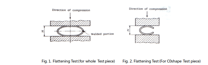
5.2 Flattening Resistance
The tube shall be tested in accordance with 9.3 and shall be free from flaws or cracks on its wall surfaces. The distance between the flattening plates in this test shall be in accordance with the following formula.

H: distance between flattening plates (mm) t: wall thickness of tube (mm)
D: outside diameter of tube(mm)
e: constant individually decided according to the class of tube
STB340 for 0.09
STB410 for 0.08
STB510 for 0.07
5.3When in the test of 9. he tube is flared into a bell shape 1.2 times the outside diameter. no flaws shall be generated.
5.4When in the test of 9.5 the electric resistance welded steel tube is subjected to reverse flattening test, flows, cracks or the like shall not be generated on the weld.
6.Hydrostatic Characteristic or Nondertructive Characteristic
The tube shall be tested in accordance with 9.6 and the resulting hydrostatic characteristic or nondestructive characteristic shall conform to either of the following two. The preference shall be in accordance with the designation made by the purchaser or left to the discretion of the manufacturer.
6.1Hydrostatic Characteristic
When a hydrostatic pressure specified by the purchaser or, unless otherwise specified, the pressure P (10 MPa at the maximum) calculated from the formula given below is applied, the tube shall withstand it without leakage.
In this case, the purchaser may specify values of pressure lower or higher than the pressure P.
When a hydrostatic pressure test is made in compliance with the designation of the purchases and the test pressure exceeds either 10 MPa or the value P calculated from the following formula, the pressure shall be agreed upon by the purchaser and the manufacturer. The designated hydrostatic test pressure shall be graduated in 0.5 MPa for the pressure values of under 10MPa and in 1 MPa for the pressure values of 10 MPa or over.
The value P in the following formula shall be obtained by computing to the unit digit and rounding off to the nearest 0.5MPa or 1 MPa.
Where
P: test pressure (MPa)
t: wall thickness of tube (mm)
D: outside diameter of tube (mm)
s: 60% of the minimum value of yield point or proof stress specified in Table 4 (N/П)
6.2 Nondestructive Characteristic Either an ultrasonic examination or an eddy current examination shall be made on the tube, and there shall be no signal greater than those produced by the artificial defects of the reference test block of either the division UD of the working sensitivity specified in JIS G 5082 or of the division EY of the working sensitivity specified in JIS G 0583, respectively.
7.Appearance
(1)The tube shall be practically straight and its both ends shall be at right angles to its axis.
(2)The inside and outside surfaces of the tube shall be well-finished and free from defects injurious to use. However, in the case of electric resistance welded tube the swelling of inside surface of the weld shall be 0.25mm or less. In this case, if necessary, the purchaser may specify the inside swelling as 0.5mm or less for the tubes 50.8mm or under in outside diameter and at the same time 3.5mm or under in wall thickness.
8.Dimensions, Mass and Dimensional Tolerances
8.1Dimensions and Mass The outside diameter, wall thickness and mass of the tube shall be as specified in Attached Table unless otherwise designated.
8.2Dimensional Tolerances The dimensional tolerances of the tube shall be as follows
(1)The tolerances on the outside diameter of the tube shall be as specified in Table 5
(1) The tolerances on the outside diameter
Table 5 Tolerances on Outside Diameter Unit: mm
| Division of outside diameter | Tolerances on outside diamete | |||
| Hot finished seamless steel tube | Cold finished seamless steel tube | Electric resistance welded steel tube other than cold finished | Cold finished electric resistance welded steel tube | |
| Under 25 |
+0.4 -0.8 |
【0.10 | 【1.5 | 【0.10 |
| 25 or over to and excl. 40 | 【0.15 | 【0.20 | 【0.15 | |
| 40or over to and excl. 50 | 【0.20 | 【0.25 | 【0.20 | |
| 50 or over to and excl 60 | 【0.25 | 【0.30 | 【0.25 | |
| 60 or over to and excl. 80 | 【0.30 | 【0.40 | 【0.30 | |
| 80 or over to and excl. 100 | 【0.40 | +0.40 | 【0.40 | |
| -0.60 | ||||
| 100 or over to and excl.12 |
+0.4 -1.2 |
+0.40 -0.60 |
+0.40 -0.80 |
+0.40 |
| -0.60 | ||||
| 120 or over to and excl.160 |
+0.40 -0.80 |
+0.40 -1.00 |
+0.40 | |
| -0.80 | ||||
| 160 or over to and excl.200 | +0.4 | +0.40 | +0.40 | +0.40 |
| -1.8 | -1.20 | -1.20 | -1.20 | |
| 200 or over | +0.4 | +0.40 | +0.40 | +0.40 |
| -2.4 | -1.60 | -1.60 | -1.60 | |
To the tolerances on the outside diameter of the electric resistance welded steel tube other than cold finished, the tolerances for the cold finished steel tube may be applied, as required by the purchaser.
(2) The Tolerances on the wall thickness and on the thickness disparity
Table 6 olerances on the wall thickness
| Tolerances |
Division of wall thickness (mm) |
Division of method of manufacture | Hot finished seamless steel tube | Cold finished seamless steel tube | Electric resistance welded steel tube | |||
| Division of outside diameter (mm) | Under 100 | 100 or over | Under 40 | 40 or over | Under 40 | 40 or over | ||
| Tolerances on wall thickness % | Under 2 | --- | --- | +0.4mm |
+22 0 |
+0.3 |
+18 0 |
|
| 0 | 0 | |||||||
| 2 or over to and excl. 2.4 | +40 | --- |
+20 0 |
+18 0 |
||||
| 0 | ||||||||
| 2.4 or over to or excl. 3.8 | +35 | +35 | ||||||
| 0 | 0 | |||||||
| 3.8 or over to or excl. 4.6 | +33 | +33 | ||||||
| 0 | 0 | |||||||
| 4.6 or over | +28 | +28 | ||||||
| 0 | 0 | |||||||
|
Tolerances on thickness disparity% |
--- | Within 22.8 of wall thickness | --- | --- | ||||
The term "thickness disparity" means the ratio of the difference between the maximum and the minimum of the measured wall thickness in the same section to the ordered wall thickness and this is not applicable to the tube under 5.6mm in wall thickness.
(3) The tolerances on the length
Table 7 Tolerances on the length
| Division | Tolerance on length | ||
|
50 mm or under in outside diameter |
7 m or under in length | +0.7 mm | |
| 0 | |||
| Over 7 m in length | Add 3 mm to the plus side permissible deviation given above for each increase of 3m or its fraction in length. However, the maximum value shall be 15 mm. | ||
|
Over 50 mm in outside diameter |
7 m or under in length | +10mm | |
| 0 | |||
| Over 7 m in length | Add 3 mm to the plus side permissible deviation given above for each increase of 3m or its fraction in length. However, the maximum value shall be 15mm. | ||
Attached Table. Dimensions and Mass of Carbon Steel Tubes for Boiler and Heat Exchanger Unit: kg/m
| 1.2 | 1.6 | 2.0 | 2.3 | 2.6 | 2.9 | 3.2 | 3.5 | 4.0 | 4.5 | |
| 15.9 | 0.435 | 0.564 | 0.686 | 0.771 | 0.853 | 0.930 | ||||
| 19.0 | 0.527 | 0.687 | 0.838 | 0.947 | 1.05 | 1.15 | ||||
| 21.7 | 0.607 | 0.793 | 0.972 | 1.10 | 1.22 | 1.34 | 1.46 | |||
| 25.4 | 0.716 | 0.939 | 1.15 | 1.31 | 1.46 | 1.61 | 1.75 | 1.89 | ||
| 27.2 | 0.769 | 1.01 | 1.24 | 1.41 | 1.58 | 1.74 | 1.89 | 2.05 | 2.29 | |
| 31.8 | 0.906 | 1.19 | 1.47 | 1.67 | 1.87 | 2.07 | 2.26 | 2.44 | 2.74 | 3.03 |
| 34.0 | 1.28 | 1.58 | 1.80 | 2.01 | 2.22 | 2.43 | 2.63 | 2.96 | 3.27 | |
| 38.1 | 1.44 | 1.78 | 2.03 | 2.28 | 2.52 | 2.75 | 2.99 | 3.36 | 3.73 | |
| 42.7 | 2.01 | 2.29 | 2.57 | 2.85 | 3.12 | 3.38 | 3.82 | 4.24 | ||
| 45.0 | 2.12 | 2.42 | 2.72 | 3.01 | 3.30 | 3.58 | 4.04 | 4.49 | ||
| 48.6 | 2.30 | 2.63 | 2.95 | 3.27 | 3.58 | 3.89 | 4.40 | 4.89 | ||
| 50.8 | 2.41 | 2.75 | 3.09 | 3.43 | 3.76 | 4.08 | 4.62 | 5.14 | ||
| 54.0 | 2.56 | 2.93 | 3.30 | 3.65 | 4.01 | 4.36 | 4.93 | 5.49 | ||
| 57.1 | 2.72 | 3.11 | 3.49 | 3.88 | 4.25 | 4.63 | 5.24 | 5.84 | ||
| 60.3 | 2.88 | 3.29 | 3.70 | 4.10 | 4.51 | 4.90 | 5.55 | 6.19 | ||
| 63.5 | 3.47 | 3.90 | 4.33 | 4.76 | 5.18 | 5.87 | 6.55 | |||
| 65.0 | 3.56 | 4.00 | 4.44 | 4.88 | 5.31 | 6.02 | 6.71 | |||
| 70.0 | 3.84 | 4.32 | 4.80 | 5.27 | 5.74 | 6.51 | 7.27 | |||
| 76.2 | 4.19 | 4.72 | 5.24 | 5.76 | 6.27 | 7.12 | 7.96 | |||
| 82.6 | 6.27 | 6.83 | 7.75 | 8.67 | ||||||
| 88.9 | 6.76 | 7.37 | 8.37 | 9.37 | ||||||
| 101.6 | 8.47 | 9.63 | 10.8 | |||||||
| 114.3 | 10.9 | 12.2 | ||||||||
| 127.0 | 12.1 | 13.6 | ||||||||
| 139.8 |
| 5.0 | 5.5 | 6.0 | 6.5 | 7.0 | 8.0 | 9.5 | 11.0 | 12.5 | |
| 15.9 | |||||||||
| 19.0 | |||||||||
| 21.7 | |||||||||
| 25.4 | |||||||||
| 27.2 | |||||||||
| 31.8 | |||||||||
| 34.0 | 3.58 | ||||||||
| 38.1 | 4.08 | 4.42 | |||||||
| 42.7 | 4.65 | 5.05 | 5.43 | ||||||
| 45.0 | 4.93 | 5.36 | 5.77 | 6.17 | |||||
| 48.6 | 5.38 | 5.85 | 6.30 | 6.75 | 7.18 | ||||
| 50.8 | 5.65 | 6.14 | 6.63 | 7.10 | 7.56 | 8.44 | 9.68 | 10.8 | 11.8 |
| 54.0 | 6.04 | 6.58 | 7.10 | 7.61 | 8.11 | 9.07 | 10.4 | 11.7 | 12.8 |
| 57.1 | 6.42 | 7.00 | 7.56 | 8.11 | 8.65 | 9.69 | 11.2 | 12.5 | 13.7 |
| 60.3 | 6.82 | 7.43 | 8.03 | 8.62 | 9.20 | 10.3 | 11.9 | 13.4 | 14.7 |
| 63.5 | 7.21 | 7.87 | 8.51 | 9.14 | 9.75 | 10.9 | 12.7 | 14.2 | 15.7 |
| 65.0 | 7.40 | 8.07 | 8.73 | 9.38 | 10.0 | 11.2 | 13.0 | 14.6 | 16.2 |
| 70.0 | 8.01 | 8.75 | 9.47 | 10.2 | 10.9 | 12.2 | 14.2 | 16.0 | 17.7 |
| 76.2 | 8.78 | 9.59 | 10.4 | 11.2 | 11.9 | 13.5 | 15.6 | 17.7 | 19.6 |
| 82.6 | 9.57 | 10.5 | 11.3 | 12.2 | 13.1 | 14.7 | 17.1 | 19.4 | 21.6 |
| 88.9 | 10.3 | 11.3 | 12.3 | 13.2 | 14.1 | 16.0 | 18.6 | 21.1 | 23.6 |
| 101.6 | 11.9 | 13.0 | 14.1 | 15.2 | 16.3 | 18.5 | 21.6 | 24.6 | 27.5 |
| 114.3 | 13.5 | 14.8 | 16.0 | 17.3 | 18.5 | 21.0 | 24.6 | 28.0 | 31.4 |
| 127.0 | 15.0 | 16.5 | 17.9 | 19.3 | 20.7 | 23.5 | 27.5 | 31.5 | 35.3 |
| 139.8 | 18.2 | 19.8 | 21.4 | 22.9 | 26.0 | 30.5 | 34.9 | 39.2 |
W: unit mass of tube (Kg/m)
t: wall thickness of tube (mm)
D: outside diameter of tube (mm)
In transaction, the unit mass of tube shall be the value given in the above table increased by 15% for the hot finished seamless steel tube, b 10% for cold finished seamless steel tube, and by 9% for electric resistance welded steel tube.
9.Test
9.1Chemical Analysis
9.1.1Chemical Analysis
General matters of chemical analysis and method of sampling specimens for analysis shall be in accordance with 3. in JIS G 0303.
9.1.2Analytical Method The analytical method shall be in accordance with one of the following Standards. JIS G 1211,JIS G 1212 ,JIS G1213, JIS G 1214, JIS G 1215 ,JIS G 1253 ,JIS G 1256, JIS G 1257.
9.2Tensile Test
9.2.1Test piece
The test specimen shall be No. 11, No. 12 A, No. 12 B or N. 12 C test piece specified in JIS Z 2201 and shall be out off from the tube in the longitudinal direction of the tube.
9.2.2 Test method
The Test method shall be in accordance with JIS Z 2241.
9.3 Flattening Test
9.3.1 Test pieces
A test piece 50 mm or over in length shall be cut off from the end of a tube. For the tube whose wall thickness is 15% or over of the outside diameter, a C-shape test piece made by removing part of the circumference of a whole test piece may be used.
9.3.2The test piece shall be placed at ordinary temperature between wo flat plates and flattened by compression until the distance between the plates comes to the specified value, and checked for the occuence of flaws or cracks on its wall surface. For the electric resistance welded steel tube, the weld shall be placed at right angels to the direction of compression as shown in fig. 1., and the C-shape test piece shall be placed as shown in Fig.2.
9.4 Flaring Test
9.4.1 An adequate length of tube shall be cut off from one end of the tube as a test piece.
9.4.2 Method of Test
The test piece shall be flared at one of the tube ends at ordinary temperature into a bell shape and to the specified size with conical tool forming an angel of 60∑and checked for any flows or other defects.
9.5 Reverse flattening Test
9.5.1 Test pieces
A length of 100 mm shall be cut off from one end of the tube as a test piece.
9.5.2 Method of Test
The test piece shall be split in the direction of tube axis on the opposite side of weld line. opened up, flattened and then checked for any flaws, cracks or other defects injurious to use that may have occurred in the weld.
9.6 Hydrostatic Test or Nondestructive Examination
Either a hydrostatic test or a nondestructive examination shall be made in accordance with (1) or (2), respectively.
(1)The tube shall be subjected to a hydrostatic pressure and kept at the designated or specified pressure to see if it withstands the pressure without leakage.
(2)The method of nondestructive examination shall be in accordance with either JIS G 0582 or JIS G 0583
10. Inspection
(1)General matters of inspection shall be as specified in JIS G 0303.
(2) The chemical composition, mechanical properties, hydrostatic or nondestructive characteristic, appearance and dimensions shall conform to the requirements specified in 3., 4., 5., 6. and 7. However, appropriate nondestructive examination other than those specified in appropriate nondestructive examination other than those specified in 9.6 (2) may substitute for the said examination when agreed upon by the purchaser and the manufacturer.
Further, when the supplementary quality requirements given in Appendix 1 or the U-bend test given in Appendix 2 specified by agreement between the purchaser and the manufacturer, the results of inspection shall conform to the relevant requirements specified in Z 1, Z 2, Z 3 and Z 4 of Appendix 1 as well as those specified in Appendix 2.
(3)Either the hydrostatic test or the nondestructive examination shall be performed for each tube.
(4)The number of specimens for the product analysis shall be agreed upon by the purchaser and the manufacturer.
(5)The method of sampling the specimens and the number of test pieces for the tensile test, flattening test and flaring test shall be as follows. Take one specimen from each 50 or its fraction of tubes as manufactured of the same dimensions (), and one specimen from each 50 or its fraction of tubes to be heat-treated of the same dimensions () and the concurrent heat treatment and then take one tensile test piece from this specimen. Further, take one flattening test piece from one end of the specimen and one flaring test piece from the other end.
Note () The "same dimensions" means the "same outside diameter combined with the same wall thickness".
11.Reinspection
The tube may apply for a retest specified in 4.4 of JIS G 0303 for final acceptance.
12. Marking
Each tube having passed the inspection shall be marked with the following items. However, the order of arranging the items is not specified. Further, in the case of either smaller tubs or request from the purchaser, the tubes may be bundled together and marked for each bundle by a suitable means.
(1) Class symbol
(2) Letter symbol indication the manufacturing method ()
(3) Dimensions
(4) Manufacturer's name or its abbreviation
(5) Letter symbol Z indicating the designation of special quality requirements
Note () Symbols for indicating the manufacturing method shall be as follows. However, - may be replaced by a blank.
Hot finished seamless steel tube -S –H
Cold finished seamless steel tube -S –C
Electric resistance welded steel tube other than Hot finished and cold finished -E –G
Hot finished electric resistance welded steel tube -E –H
Cold finished electric resistance welded steel tube -E -C
13. Report
The manufacturer shall, in general, submit to the purchaser a detailed statement of the test results, method of manufacture, ordered dimensions, quantity, work number indicating the history of manufacture, etc.
Appendix 1 Supplementary Quality Requirements
The supplementary quality requirements shall apply only when required by the purchaser and shall be executed by the manufacture 1 for the designated items on the straight tube.
Z 1 Hardness
(1)The hardness of the tube shall be as given in Appendix 1 Table 1-1 or Table 1-2.
Appendix 1 Table 1-1, Hardness
| Symbol of class | Rockwell hardness HRB (Mean value of three points) |
|
STB 340 STB 410 STB 510 |
77 max. 79 max. 92 max. |
(2)A suitable length shall be cut off from one end of the tube.
(3)The test method shall be in accordance with JIS Z 2245 and the hardness on the cross section or inside surface of the test piece shall be measured at three points for each test piece.
Further, a tube under 2 mm in wall thickness shall not be tested. As for the electric resistance welded steel tube, the test shall be performed in the portion other than the weld and the heat-effected zone.
(4)The hardness shall comply with the requirement specified in Appendix 1 Table 1-1 or able 1-2.
(5)The sampling of specimens and the number of test pieces shall be as specified for the tensile test in 10.1(5) of the text.
(6)Reinspection
The tube may be put to a retest specified in 4.4 of JIS G 0303 for final acceptance.
Z 2 Elevated Temperature Yield Point or Proof Stress
(1)The value of elevated temperature yield point or proof stress and the testing temperature of the pipe shall be agreed upon by the purchaser and the manufacturer.
(2)The test piece and the test method shall be as specified in JIS G 0576 However, when it is practically difficult to take the test piece of the shape specified in JIS G 0575, the shape of the test piece shall be agreed upon by the purchaser and the manufacturer.
(3)The method of sampling the test specimens and the number of test pieces shall be as follows. Take one test specimen from each lot of the same testing temperature.
Z 3 Ultrasonic Examination
(1)The criteria of the working sensitivity in the ultrasonic examination shall be the division UA or UC specified in JIS G 0582, and there shall be no signal greater than those produced by the artificial defects of the reference test block.
(2)The test method of the ultrasonic examination shall be as specified in JIS G 0582.
(3)The ultrasonic examination shall be performed for each tube and the results shall conform to the requirements specified in (1).
Z 4 Eddy Current Examination
(1)The criteria of the working sensitivity in the eddy current examination shall be the division EV , EW or EX specified in JIS G 0583, and there shall be no signal greater than those produced by the artificial defects of the reference test block.
(2)The test method of the eddy current examination shall be as specified in JIS G 0583.
(3)The eddy current examination shall be performed for each tube and the results shall conform to the requirements specified in (1).
Appendix 2 U-bend Tubes
The U-bend tube shall be applied when the purchaser requires it and shall be executed by the Manufacturer.
1. Method of Manufacture
The method of manufacture shall be as follows (See Appendix 2 Fig.).
(1)The U-bend tube shall be made by old bending process and the bending radius shall be at least 1.5 times the outside diameter of the tube.
(2)The bent portion of the tube shall, in general, not be heat-treated.
However, when required by the purchaser, the heat treatment may be agreed upon. 2.The bent portion shall be free from defects injurious to use.
3.The dimensional tolerances on the bent portion shall be as specified in Appendix 2 Table 1 and the tolerances on length after bending shall be as specified in Appendix 2 Table 2.
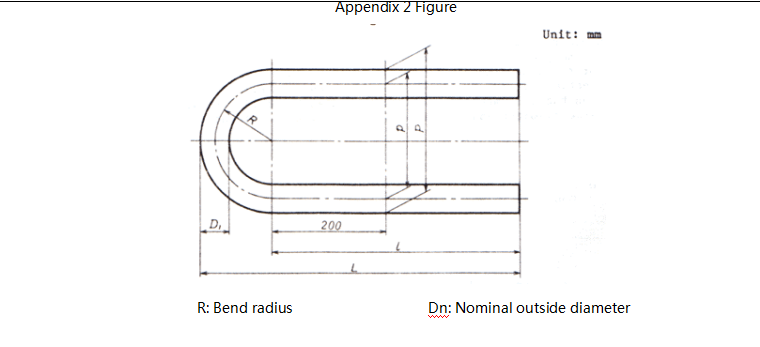
D: Outside diameter of bent portion
t: Minimum wall thickness of bent portion P: p+Dn
L: ラ +R+Dn/2
tn: Nominal wall thickness p: Pitch
ラ : Length of straight portion
Appendix 2 Table 1. Dimensional Tolerances on Bent Portion
|
Variation of outside diameter D1-Dn /Dn X100% |
Reduction rate of wall thickness tn-t1 /tn X100% |
Tolerance on pitch (p) or P mm |
|
| Short radius side | Long radius side | ||
|
Dn /4R X100 max However, minimum value 0.5 mm |
Dn /8R X100 max However, minimum value 0.5 mm |
Dn /2.5R X100 max |
【1.5 |
Appendix 2 Table 2. Tolerances on Length of U-Bend Tube
| Division of length | Tolerances on length (ラ or L) mm |
|
7 m or under in length of straight portion after bending |
+7 0 |
|
Over 7 m in length of straight portion after bending |
+10 0 |
4.The measurement of dimensions of bent portion shall be carried out as follows. Take on specimen from U-bend tube with the smallest bending radius of the tubes of the same dimensions bent concurrently, Measure the outside diameters in two directions at 90x to bent portion and he wall thickness at four locations on the circumference and then obtain the variation rate of outside diameter and the reduction rate of wall thickness.
![field:title/]](/uploads/260311/1-2603111FA1548.png)
![field:title/]](/uploads/251210/1-251210164114F6.png)
![field:title/]](/uploads/241211/1-241211152454213.png)
![field:title/]](/uploads/220425/1-22042511053I30.jpg)
![field:title/]](/uploads/220414/1-220414214051492.jpg)
![field:title/]](/uploads/211104/1-211104121004V0.jpg)
![field:title/]](/uploads/211102/1-21110215254UP.jpg)
![field:title/]](/uploads/210923/1-2109231045325B.png)