ASTM B163 Incoloy 800HT(UNS N08811)Seamless Tube
ASTM B163 Incoloy 800HT(UNS N08811)Seamless Tube
Standard: ASTM B163
Specification for Seamless Nickel and Nickel Alloy Condenser and Heat-Exchanger Tubes
ASTM B163 Incoloy 800HT(UNS N08811) Seamless Tube for use in condenser and heat-exchanger service.
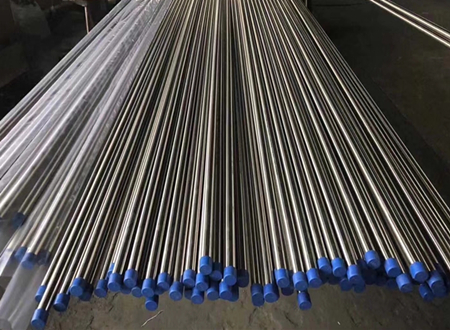
ASTM B163 Incoloy 800HT(UNS N08811) Seamless Tube Quick Details
Manufacture:Seamless process ,annealed
Wall thickness(WT): 1.24 mm-40.49 mm.
Outer diameter (OD): 10.3 mm-426 mm
Delivery Condition:Pickled&Annealed, Polished, Bright Annealed.
Length: 6M or specified length as required.
Ends: Plain End, Beveled End, Treaded
Additional Info
Port of Shipment: Any Port, China
Payment Terms: T / T, LC
Delivery: 25 days after payment
Surface: Tubes will be varnished to prevent rust.
Marking: Standard + Steel Grade + Size + Heat No + Lot No
Package: Bundles (hexagonal),Wooden Boxes,Crates (steel/wooden) or as required
Manufacture
The Tubes are made by the seamless process and The Tube will be furnished in the alloys and conditions as shown in Table 1.
| Alloy | Condition |
| Nickel-iron-chromium alloy UNS N08811 | annealed |
Chemical Composition of ASTM B163 Incoloy 800HT(UNS N08811)
The material shall conform to the composition limits specified in Table 2.
| Composition,% | |
| Grade | N08811 |
| Nicke | 30.0–35.0 |
| Copper | 0.75 |
| Molybdenum | ... |
| Iron | 39.5 min B |
| Manganese | 1.5 |
| Carbon | 0.06–0.10 |
| Silicon | 1.0 |
| Sulfur | 0.015 |
| Chromium | 19.0–23.0 |
| Aluminum | 0.15–0.60 C |
| Titanium | 0.15–0.60 C |
| Phosphorus | ... |
| Cerium | ... |
| Zirconium | ... |
| Yttrium | ... |
| Boron | ... |
| Cobalt | ... |
| Columbium(Nb) | ... |
| Tungsten | ... |
| Nitrogen | ... |
Mechanical Properties and Other Requirements of of ASTM B163 Incoloy 800HT(UNS N08811)
Mechanical Properties—The material shall conform to the mechanical properties specified in Table 3.
| Material and Condition |
Tensile Strength, min, ksi (MPa) |
Yield Strength (0.2 % Offset), min, ksi (MPa) |
Elongation in 2 in.or 50 mm (or4 D)min, % |
Rockwell Hardness (or equivalent) for annealed ends A |
| Nickel-iron-chromium alloys:nnealed alloy UNS N08811 | 65 (448) | 25 (172) | 30 | ... |
Note: Rockwell or equivalent hardness values apply only to the annealed ends of stress-relieved tubing. Caution should be observed in using the Rockwell test on thin material,as the results may be affected by the thickness of specimen. For thickness under 0.050 in. (1.27 mm) the use of the Rockwell superficial or the Vickers hardness test is suggested. For hardness conversions for nickel and high-nickel alloys see Hardness Conversion Tables E140.
In the case of stress-relieved tubes furnished with annealed ends, the tension test shall be made on the stressrelieved tubes prior to annealing the ends.
Testings
Chemical Analysis
Mechanical Properties
Grain Size—A transverse sample representing full-wall thickness of annealed alloys UNS N08811 shall conform to an average grain size of ASTM No. 5 or coarser.
Hardness test—When annealed ends are specified for tubing in the stress-relieved condition (see Table 3), the hardness of the ends after annealing shall not exceed the values specified in Table 3.
Flare test—A flare test shall be made on one end of 1 % of the number offinished tube lengths from each lot.
The flare test shall consist of flaring a test specimen with an expanding tool having an included angle of 60° until the specified outside diameter has been increased by 30 %. The flared specimen shall not exhibit cracking through the wall.
Hydrostatic or Nondestructive Electric Test—Each tube shall be subjected to either the hydrostatic test or the nonde-structive electric test. The type of test to be used shall be at the option of the manufacturer, unless otherwise specified in the purchase order.
Hydrostatic Test:
Each tube with an outside diameter 1 ⁄ 8in. (3.2 mm) and larger and tubes with wall thickness of0.015 in. (0.38 mm) and over shall be tested by the manufacturer to an internal hydrostatic pressure of 1000 psi (6.9 MPa) provided that the fiber stress calculated in accordance with the following equation does not exceed the allowable fiber stress, S, indicated below. The tube shall show no evidence of leakage.

P = hydrostatic test pressure, psi (MPa),
S = allowable fiber stress for material in the condition furnished, as follows:
| psi | MPa | |
| Annealed nickel-iron-chromium alloy UNS N08811 | 16 600 | 114.4 |
D = outside diameter of the tube, in. (mm).
When stress-relieved tubes with annealed ends are to be tested hydrostatically, such pressure testing shall be done prior to annealing of the ends of the tube.
Dimensions and Permissible Variations
Outside Diameter and Wall Thickness—The permissible variations in the outside diameter and wall thickness of tube shall not exceed those prescribed in Table 4 as applicable. (See also Table 5 and Table 6.)
N OTE 2—Eccentricity—The variation in wall thickness in any one cross section of any one tube shall not exceed plus or minus 10 % of the actual (measured) average wall of that section. The actual average wall is defined as the average of the thickest and thinnest wall of that section.
| Material | Nominal Outside Diameter, in. (mm) | Permissible Variations A | |||||
| Outside Diameter, in. (mm | Wall Thickness,% | ||||||
| + | − | Average Wall | Minimum Wall | ||||
| + | - | + | - | ||||
|
UNS N02200, UNS N02201, and UNS N04400 |
1 ⁄ 2 to 5 ⁄ 8 (12.7 to 15.9), excl | 0.005 (0.13) | 0 | 12.5 | 12.5 | 25.0 | 0 |
| 5 ⁄ 8 to 1 1 ⁄ 2 (15.9 to 38.1), incl | 0.005 (0.13) | 0.005 (0.13) | 10.0 | 10.0 | 20.0 | 0 | |
| over 1 1 ⁄ 2 to 3 (38.1 to 76.2), incl | 0.010 (0.25) | 0.010 (0.25) | 10.0 | 10.0 | 22.0 | 0 | |
|
UNS N06600, UNS N06601, UNS N06690,UNS N06045, UNS N06025, UNS N06603, UNS N06696, UNS N08800, UNS N06699 UNS N08810, UNS N08811, UNS N08801, UNS N08935 UNS N08825, UNS N06845, and UNS N08120 UNS N06686 |
1 ⁄ 2 to 5 ⁄ 8 (12.7 to 15.9), excl | 0.005 (0.13) | 0.005 (0.13) | 12.5 | 12.5 | 25.0 | 0 |
| 5 ⁄ 8 to 1 1 ⁄ 2 (15.9 to 38.1), incl | 0.0075 (0.19) | 0.0075 (0.19) | 10.0 | 10.0 | 20.0 | 0 | |
| over 1 1 ⁄ 2 to 3 (38.1 to 76.2), incl | 0.010 (0.25) | 0.010 (0.25) | 10.0 | 10.0 | 22.0 | 0 | |
A Wall variations as indicated above are applicable only to the wall as ordered, for instance, to minimum or to average wall, but not to both.
| Tube OD, in. (mm) | Average Tube Wall, in. (mm)B | Minimum Bend Radius, in.(mm) | |
|
Annealed Condition |
Stress-Relieved Condition |
||
| Up to 1 ⁄ 2 (12.7), incl | 0.046 to 0.057 (1.17 to 1.45), incl | 1 3 ⁄ 1 6 (30.2) | 1 1 ⁄ 4 (31.8) |
| Up to 1 ⁄ 2 (12.7), incl | Over 0.057 to 0.120 (1.45 to 3.05), incl | 1 (25.4) | 1 1 ⁄ 8 (28.6) |
| Over 1 ⁄ 2 to 5 ⁄ 8 (12.7 to 15.9), incl | 0.037 to 0.057 (0.94 to 1.45), incl | 1 3 ⁄ 1 6 (30.2) | 1 1 ⁄ 4 (31.8) |
| Over 1 ⁄ 2 to 5 ⁄ 8 (12.7 to 15.9), incl | Over 0.057 to 0.120 (1.45 to 3.05), incl | 1 (25.4) | 1 3 ⁄ 1 6 (30.2) |
| Over 5 ⁄ 8 to 3 ⁄ 4 (15.9 to 19.0), incl | 0.049 to 0.057 (1.24 to 1.45), incl | 1 1 ⁄ 4 (31.8) | 1 1 ⁄ 2 (38.1) |
| Over 5 ⁄ 8 to 3 ⁄ 4 (15.9 to 19.0), incl | Over 0.057 to 0.109 (1.45 to 2.77), incl | 1 3 ⁄ 1 6 (30.2) | 1 1 ⁄ 4 (31.8) |
| Over 3 ⁄ 4 to 1 (19.0 to 25.4), incl | 0.049 to 0.058 (1.24 to 1.47), incl | 2 (50.8) | 4 (101.6) |
| Over 3 ⁄ 4 to 1 (19.0 to 25.4), incl | Over 0.058 to 0.109 (1.47 to 2.77), incl | 1 3 ⁄ 4 (44.5) | 2 1 ⁄ 4 (57.2) |
B To determine the bend radius applicable to minimum wall tubing,compute the corresponding average wall from the wall tolerances in Table 4, then use Table 5.
| Alloys | Size Range, in. (mm) | 0.2 % Yield Strength, ksi (MPa) | ||
| OD | Wall Thickness | Minimum | Maximum | |
| Nickel-chromium-iron Alloy UNS N06600 | 1 ⁄ 4 to 7 ⁄ 8 (6.35 to 22.23) | Up to 0.100 (2.54) | 40 (276) | 65 (448) |
| Nickel-chromium-iron Alloy UNS N06601 | 1 ⁄ 4 to 7 ⁄ 8 (6.35 to 22.23) | Up to 0.100 (2.54) | 40 (276) | 65 (449) |
| Nickel-iron-chromium Alloy UNS N08800 | 1 ⁄ 4 to 7 ⁄ 8 (6.35 to 22.23) | Up to 0.100 (2.54) | 40 (276) | 65 (448) |
| Nickel-chromium-iron Alloy UNS N06690 | 1 ⁄ 4 to 7 ⁄ 8 (6.35 to 22.23) | Up to 0.100 (2.54) | 40 (276) | 65 (448) |
Length—When tube is ordered cut-to-length, the length shall not be less than that specified, but a variation of plus 1 ⁄ 8 in. (3.2 mm) will be permitted, except that for lengths over 30 ft (9.1 m), a variation ofplus 1 ⁄ 4 in. (6.4 mm) will be permitted.
Straightness—Material shall be reasonably straight and free of bends or kinks.
Workmanship, Finish, and Appearance
The material shall be uniform in quality and temper,smooth, commercially straight, and free of injurious imperfections.
Certification
When specified in the purchase order or contract, a report of the test results will be furnished.
Note:
All tubes shall be supplied as per applicable ASTM B163 /B163M Specification
Mill test certificates will be issued
We can provide 3.2 Certification according to the needs of you
![field:title/]](/uploads/230113/1-2301131I345550.jpg)
![field:title/]](/uploads/230113/1-2301131H026163.jpg)
![field:title/]](/uploads/230113/1-2301131G9203a.jpg)
![field:title/]](/uploads/230113/1-230113163PU05.jpg)
![field:title/]](/uploads/230113/1-2301131634242G.jpg)
![field:title/]](/uploads/230113/1-2301131626113H.jpg)
![field:title/]](/uploads/230113/1-230113161JB49.jpg)